Objective:
Create a circuit that uses a button to simultaneously control both an LED and a motor. This puzzle will introduce you to basic parallel circuits and how one control (the button) can influence multiple components in an electronic system.
Overview:
In this puzzle, you will wire a button to control both an LED and a motor at the same time. This setup demonstrates how a single input (button press) can manage multiple outputs (LED and motor), offering a practical example of parallel circuits in action.
Components Needed:


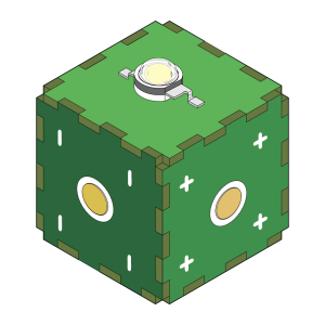
- 1 LED
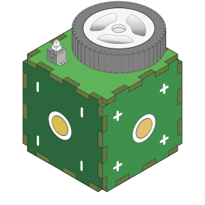
- 1 Motor
- 1 Button
Remember
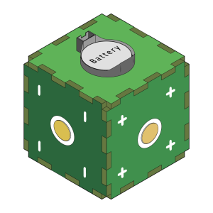
You can use as many cubes as you like to make the connection between Circubes. Use magnet cables to create initial design but you should not use any cable but Circubes to create the circuit
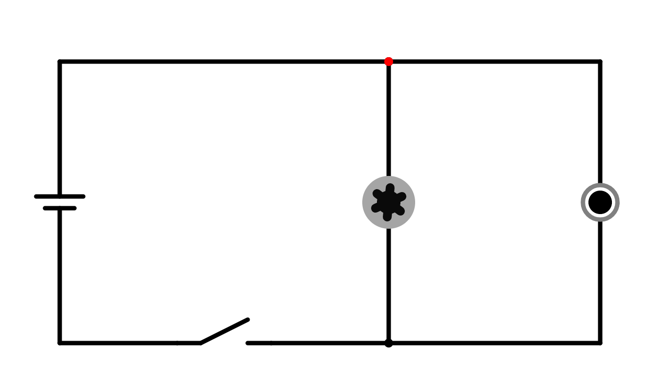
Circuit Diagram:

Instructions:
- Circuit Design Overview:
This circuit will use the button as a common control to turn both the LED and motor on and off simultaneously. When the button is pressed, both components will receive power and activate. This setup demonstrates the concept of parallel circuits, where multiple components share the same power source. - Build the Circuit:
- Wiring the Button:
Place the button on the breadboard and connect one terminal of the button to the positive terminal of the battery. - Connecting the LED:
Connect one end of the 330Ω resistor to the other terminal of the button. Connect the other end of the resistor to the positive leg (anode) of the LED. Then, connect the negative leg (cathode) of the LED to the negative terminal of the battery. - Connecting the Motor:
Now, connect the other terminal of the button directly to one of the terminals of the motor. If required, you can place a 100Ω resistor in series with the motor to limit the current and protect the motor. Then, connect the other terminal of the motor to the negative terminal of the battery.
- Wiring the Button:
- How It Works:
- Button as a Switch:
When you press the button, current flows through both the LED and motor, turning them on simultaneously. The LED lights up because of the current flowing through it, while the motor spins due to the current flowing through it. Once you release the button, both components turn off as the circuit is broken. - Parallel Circuit Configuration:
The LED and motor are wired in parallel after the button, meaning both components share the same control (button) but are independently connected to the power source. This allows the button to control both outputs at the same time.
- Button as a Switch:
- Testing and Observations:
- Pressing the Button:
Press the button and observe how both the LED and motor turn on at the same time. When you release the button, both components should turn off. - Experiment with Different Components:
Try using different values for the resistors or different types of motors to see how they affect the performance of the circuit.
- Pressing the Button:
- Understanding Parallel Circuits:
- In a parallel circuit, multiple components share the same power source but are independently connected to it. This circuit configuration is useful when you want to control multiple outputs with a single input.
Conclusion:
You’ve successfully built a circuit that controls both an LED and a motor using a single button. This puzzle demonstrated how a parallel circuit works and how you can coordinate multiple components with one control. This concept is widely used in systems where you need to activate or deactivate multiple devices with a single action, like in alarms, systems with multiple lights, or more complex circuits.